https://nautil.us/five-things-we-still-dont-know-about-water-3383/
Monday, March 28, 2022

Saturday, February 19, 2022
How to upgrade hard drives on a Linux file server
Another in my series of blog posts about "The way I do things that fit my very specific and peculiar set of needs". I recently upgraded my HDDs in my Linux file server, and found a pattern that worked quite well with minimum disruption.
How I have things set up
I have a headless Linux server with a SSD as the primary drive, and then a few spinning HDDs for bulk media storage. All the drives are just formatted in ext4. I do backups to S3 for important files. Then, every time I upgrade the storage of these drives I copy everything to the new drive, and then remove the old drive from the machine. That old drive serves as a backup for the bulk media stuff, combined with the plan to just redownload anything I got recently.
I've never bothered with RAID or more complex file systems because they only made sense to me if I had 4 or more drives, which I've never had. This makes upgrading the drives a simple process.
My /etc/fstab file has a bunch of lines like this:UUID=9fa3b7dc-3cd7-42c1-93a8-46dcf38da09d /mnt/media ext4 defaults 0 2
And then I share those drives using NFS by putting these lines in /etc/exports:
/mnt/media 192.168.1.0/24(rw,sync,no_subtree_check,no_root_squash)
Format the new drive
Put the drive in the machine and power it on. If the drive is brand new it won't have any partition tables on it, or the UUID needed for the fstab file. Here's a bunch of commands which are useful for figuring out which drive is which:
sudo blkid
lsblk -f
sudo fdisk -l
Once you know what the path to the drive is (eg, /dev/sdb), you can use fdisk to format the drive. Be sure you have picked the right drive, because you'll wipe all your data on whatever disk you run fdisk on. Use m to see the list of fdisk commands. But both F and p are useful to confirm you have the right (empty) disk. Once you're sure you can run g to create the partition table, and then n to create the new partition. The defaults should be fine. Once you are sure you have things right, you can write your changes to the disk with w.
You now need to create the ext4 filesystem on your partition. Do that with sudo mkfs.ext4 /dev/sdb1 making sure that your use the correct drive letter.
Mount the new drive
Now run the above commands used to identify the drives again, and hopefully you see a UUID for the new drive. Copy that UUID down and edit your fstab file with sudo nano /etc/fstab
/mnt/media_new. Then you need to make sure you create that mount point (sudo mkdir /mnt/media_new). Then you can mount the drive with sudo mount -av . Now you can poke around and make sure things look right, you probably want to update the owner with sudo chown.Copy the old data to the new drive
There are many ways you could copy the data, but I like rsync. One nice thing is that if it gets interrupted it'll pick up where it left off. Here's the command I came up with after exploring the options for a while: rsync -axHAWXS --info=progress2 /mnt/media/ /mnt/media_new/ The options largely came from here, so you can go there if you want to read what they do. That took about 12 hours for me to copy about 5 TB. While it will print out the progress, I found it much better to just ssh in on a new tab and then run df -Th and compare the disk usage of the old and new drives. After the first pass though, running it again, to make sure there wasn't anything new, only took a couple minutes.
Make the swap
This isn't a foolproof process, you should close anything that is using the disks, and run the rsync command one more time. Then you can unmount the current drive with sudo umount /dev/sda1. Now you want to edit your fstab one more time and delete the old drive's line from it, while updating the mount point of the new drive to the one the old drive was using. Now you can probably get way with just running sudo mount -av again, but I like to just shutdown (sudo shutdown -h now), and physically remove the old drive.
That's it
That's it. If all went according to plan, then everything that used the old drive previously, should now just use the new drive. I had to restart my remote machines that used the NFS drives before they would connect.
Friday, February 11, 2022
Rome: Decline and Fall?
https://acoup.blog/2022/02/11/collections-rome-decline-and-fall-part-iii-things/
But this now raises two related questions: first, why did population decline so sharply and second, what was the impact on quality of life that resulted? The old answer to the first question was of course ‘the barbarians killed everyone’ but as we’ve seen, while the fifth century was a violent time, the violent discontinuities were not that extreme. Surely the violence of the period has something to do with some of this declining population, but as noted, the underlying population (with their language and religion) didn’t much change (and the raw number of ‘barbarians’ coming over the frontier was, in demographic terms, fairly small). Most of those Roman cities decayed, rather than being burned. But if the ‘barbarians’ didn’t kill everyone, what did and why did that somehow have a negative impact on the survivors? The answers to these two questions are actually linked in that they depend on the same evidence, so that is where we will go next.
...
If you will permit me an extended metaphor, Rome wasn’t so much demolished by invaders as it was burned down by Roman arsonists who set fire to their own house – and they had been setting those fires since at least 235, long before Adrianople. The emperors of the fourth century (particularly Diocletian and Constantine) may have put out some of the fires by collapsing a wing of the house to smother them, but this can hardly be regarded as improvement, not the least because neither of them did anything to deal with the arsonists (one of which, Constantine, at least, must be reckoned). The emperors of the late fourth and fifth centuries then proceeded to invite people into the house, promising its shelter, if only they would help them light one more fire – and then when the house was burned down and everyone was left on the cold ground, they tried to shift the blame onto the very guests they had invited.
Wednesday, January 19, 2022
How GPS works
This guy goes into so much detail, with great visualizations of everything he explains. It's always a treat when he publishes a new post.
Monday, December 13, 2021
My method for backing up a Raspberry Pi
Intro
I have a vast army of Raspberry Pis serving me (although recently I've been liking ESP32 for some of the simpler tasks I've used to use Pis for, and mini PCs for the more complex ones). I just had my first SD card failure in one. This was a bit more annoying than I predicted it would be, so I set out to come up with a good automated backup process for my Pis. As with everything I do, there are plenty of good write ups about how to do this online, and you will undoubtedly find those more useful if you actually want to do this, but I will document what I did here for 1. hypothetical fellow weirdos, 2. myself from the future.
NFS Server
I have a home server, with all my bulk storage in it. I primarily run Plex and Home Assistant on it, but I also host my music collection on it, which I share out to my desktop and other clients via NFS. NFS is just the Linux version of network shared drives. I won't go into details about how to set up NFS, but this is a good overview.
Backup Script
Once you have a NFS server set up, you can just mount a drive there on your Pi with write access. I then use rsync to send directories to the network drive nightly. Here's my script along with some notes.
I chose the directories with configuration and data that I cared about in them, although it should cover most uses.Sunday, November 21, 2021
Fixing Christmas lights with a BBQ lighter
I have an old Christmas tree with several independent prewired light segments on it. About half of these segments no longer work. I figured it was just a matter of finding the blown out bulbs and replacing them. I also knew the sets always claimed that if "one blows out, the rest stay on", but in practice those claims seem to not pan out.
In researching how to find the dead bulbs I came across a product called the Light Keeper Pro. I didn't really understand how this product worked, or even really what it was supposed to do, but it was only $20, and I was confident I could fix the lights with the right tools.


The device has a lot of functions built in; it's really a Christmas light Swiss Army Knife. The one I thought I'd be using is the bulb tester, where you just pull the bulb out and stick it in the top and it'll light up if it works. There's a similar fuse tests, although the company reiterates several times that fuses are rarely the problem. There is also a non-contact voltage detector, which I have several of already, but is nice to have on there. It's only useful for faults where there is a break in the circuit, like a missing bulb, or a cut wire. There's a bulb remover tool, which I haven't really been able to figure out, and haven't tried very hard because I don't have trouble just pulling the bulbs out.
The star of the show though, is the quick fix trigger. The instructions explain you remove any bulb from a non-working section and insert the socket into the front of the device (essentially the device fits like a giant "bulb"). You then click the trigger several times, and the lights somehow come on. You do all this while the lights are plugged into the wall.
I almost skipped even trying this because it seemed so absurd. But once I figured out exactly what they wanted me to try, I did it, and it worked, over and over again. There were probably 5 different sections on this tree that didn't work, and this thing fixed each one in 30 seconds. Now, to be clear, it doesn't make blown out bulbs come back on, but it does make it so that the "one blows out, the rest stay on" function actually works. After the section comes back on you have to replace the burned out bulbs with new ones.
It may not surprise you that this led to me learning a lot about Christmas lights. Now you're going to learn a lot about Christmas lights too.
How do Christmas lights work?
They start out pretty simple. 50 bulbs, each with a resistance of about 2.5Ω are in series. Their resistances add, and so overall the string has a resistance of about 125Ω. You plug that into 120 VAC and you get about 1 amp flowing through them. You can imagine that each bulb shares an equal portion of the voltage, so each bulb has 120 / 50 = 2.4 volts across it. If you took a single bulb and put 2.4 volts across it, it'd light up the same as if it were in a set. The filament is just a piece of wire, which is so thin that it heats up very hot when the amp is flowing through it, and it glows. Eventually that filament wears out and literally burns out from the heat. At that point, the filament is gone and there is a gap which the current can't flow over. Since every bulb is in series, current can't flow at all, and the entire set goes out.

I took this picture from here and it shows the situation. If your set has more than 50 bulbs then it probably has a multiple of 50 (100, 150, etc). In that case it's just a few of these sets of 50 just all connected together at the plug, like the next picture shows.

How do "one blows out, the rest stay on" lights work?
The magic of these is entirely within the bulb. The wiring is same as above, just bulbs connected in series, but the difference is a "shunt" in the base of each bulb. The idea is that if filament burns out, then the current can instead travel over the shunt. The shunt is much thicker, so it doesn't heat up and glow.
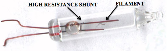

How do these shunts work?
This is the key to this entire post. The shunts can't just be another piece of wire, because all the current would just travel over that instead of the filament. They need to be "off" normally, and only get activated when the filament blows out. The shunt is just a piece of oxidized aluminum wire. The oxidation makes it high resistance, and when there is the normal 2.4 VAC across the bulb the shunt does not carry a current. If a high voltage is applied to the shunt though, the current will flow through it and the oxidation layer will burn up and you'll be left with a low resistance wire. This is called an antifuse.
How do we get a high voltage to the shunt when the filament burns out?
This just happens. I said above each bulb is sharing the 120 VAC from the wall, equally. However, if there is a gap in the circuit (like a burned out filament), then no current will flow, and the full voltage will build up at the gap. It doesn't matter how much resistance is in the circuit, if it is open, and no current is flowing, then the full voltage will be present at that gap. Therefore, when one of the filaments burns out, the shunt in that bulb gets 120 VAC across it, which is usually enough to burn up the oxide layer on it and turn it into a normal wire. Sometimes the 120 VAC isn't enough though, and that's when the whole set fails despite the "one blows out, the rest stay on" shunts.
How do we fix them?
Now that we know all that, the solution is pretty easy. Just apply a higher voltage. You could do this with some sort of high power transformer (like a ballast from a florescent light), but you'd have to apply the voltage just long enough to trigger the stubborn shunt, and if you applied it too long all the lights would burn out. You'd have milliseconds between when you fixed the shunt and you ruined the entire set.
Luckily there's a simple solution: piezoelectricity. There are certain crystals that when you hit them they produce a high voltage burst, a static electric shock on demand. Any time you press a button and there's a click and a spark that is piezoelectricity. It's how BBQ lighters work, and it's how the Light Keeper Pro works.
All that the Light Keeper Pro is doing is creating a quick burst of high voltage and putting it on the circuit. It's a weird combo of 120 VAC and few milliseconds of 15 kVDC. The 15 kilovolts easily overwhelm the AC voltage, no matter where it is in its AC cycle. The 15 kVDC would fry stuff throughout your house, except it's such a small amount of energy it is easily absorbed by the actual wires long before it can reach anything. The only thing that burst has a chance of reaching, and effecting, is the very sensitive aluminum oxide coating which is preventing the shunt from carrying current.
And that's all there is to it. You could do the exact same thing as the Light Keeper Pro with a BBQ lighter. All it is is a convenient package and way to connect the bulb socket to the piezoelectric spark.
Thursday, October 21, 2021
Friday, September 10, 2021
Suspicious discontinuities
https://danluu.com/discontinuities/
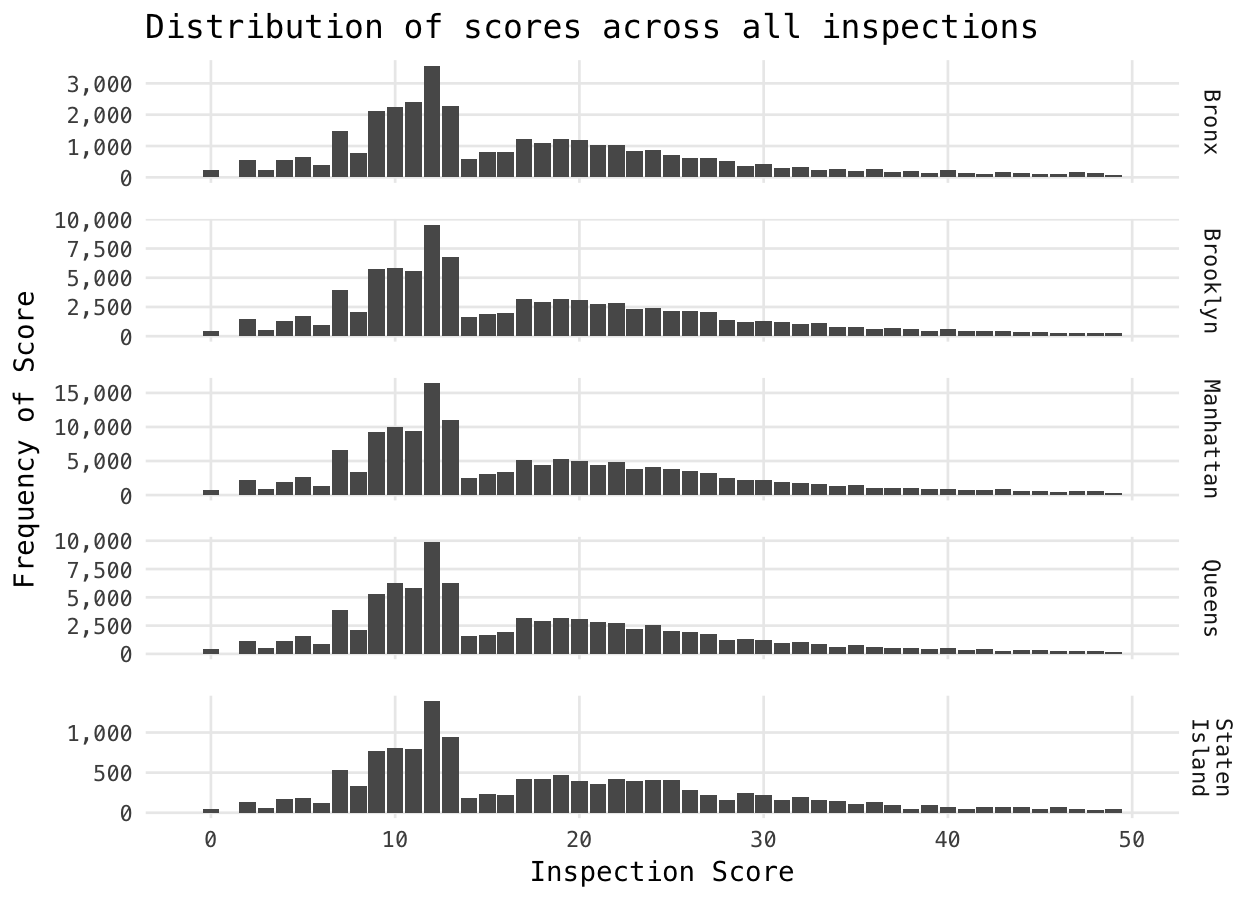
This page is a wall of text and some charts, but it shows some really interesting patterns in a wide array of data sets.
Thursday, September 2, 2021
How I DIY smart home sensors
Home Assistant
I've had a draft post about Home Assistant for years, which I haven't posted because I feel like my HA install is perpetually under construction. If you haven't heard of Home Assistant, it's a LAN based, open source, smart home control center. Typically installed on a Raspberry Pi, it has an absurd number of integrations with third parties. While the UI of HA can be polished up to be pretty nice, its real value is in automatons that never require opening the UI. This isn't a HA post so I'll stop talking about it, but I highly recommend playing around with it if you have any interest in smart home, and are willing to tinker a bit in exchange for not having to use cloud based systems.
Sensors
While I have a variety of sensors that serve particular purposes, I'm obsessed with collecting basic data for each area of my house. Particularly, I like to measure the temperature, humidity, and light level on each level on my house (including attic and basement). I do nothing with this information, but I look at the graphs literally every day, and they bring me great joy. If you're confused right now, this is probably a good time for you to cut your loses and stop reading this post. If you're excited for your own graphs, read on.
 |
| Data |
While you can buy ready made sensors that measure these things, I've always built my own. They are much cheaper, and you have way more flexibility if you decide you want to add something later. Originally I started out with Raspberry Pis, and then Rasperrry Pi Zero Ws. This works, but if you start wanting to do multiples of these, then the overheads of SD cards and high current power supplies start to add up.
I've always considered using an ESP32 (what an Arduino is based on) instead, but they are just more annoying to work with. While a Raspberry Pi is a full computer, running Linux, an ESP32 is a microcontroller, which means you write a single program (typically in C), compile it and load it up, and when it powers up it runs that program, and does nothing else.
ESPHome
While the hassle of the ESP32 has never been worth the cost savings over the Raspberry Pi for me, this all changed when I discovered a project called ESPHome. With ESPHome you connect some sensors to an ESP32, create a YAML file with the config, then upload the files to the ESP32, which will then begin sending the data to Home Assistant via an integration. I couldn't believe how slick the setup was. You can even update the config file and send the update to the ESP32 via WiFi without having to go to wherever you have it installed and hooking it up to a computer. With ESPHome, setting up these sensors is easier with ESP32s than my custom Python scripts running on Raspberry Pis.
Hardware
These links are mostly dead, as these listing change often. But, I'll provide them, and the price I paid, as a reference for you, visitor from the future.
ESP32 ($6.50 each) - There are a few versions of these out there, and I'm not an expert on the differences, but for our purposes I don't think they matter much. Just note what pin layout you get, and make sure when you buy more they are the same layout.
BME280 ($24 / 3) - Temperature, humidity, and pressure sensors. I used to use DHT22 sensors, but BME280s are: 1. more accurate, 2. use the I2C protocol, and 3. include pressure. I can put two DHT22 sensors next to each other and while it's obvious the graphs follow each other, there is clear variation between them. With two BME280s the graphs are spot on. They are also much higher resolution, which makes the graph much smoother. The I2C protocol allows you to share one pin across many sensors. Each sensor gets an address and the host will cycle through them measuring each one. This makes it quite easy to add another (I2C based) sensor later on.
BH1750 ($7 / 3) - Light sensor; also uses I2C.
USB Charger - I won't provide a link and cost for these. The power requirements for ESP32s is much lower than a Raspberry Pi, under 500 mA vs at least 1000 mA to over 2000 mA for newer Raspberry Pis. You should be able to use any random USB charger you have available.
Prototype Boards ($12 / 40) - Not required. Used to hold multiple sensors together and wire everything up.
Headers ($14 / 120) - Used with the prototype board.
Jumper / Dupont wires ($7 / 120) - Used to connect sensors. You can technically get by without these if you use the prototype boards, or you can use just these instead of the boards.
Build
Full disclosure: This isn't going to be the type of guide you can just follow along step by step and end up with something that works. You'll have to understand what you're actually doing to get this to work. This isn't intentional on my part, it's just the best I can do explaining this. If you've soldered a bit before, and are familiar with wiring things up to Pis and Arduino you should be able to get it to work.
My goal is to build a "shield" from a prototype board, which will sit on top of the ESP32 and allow multiple I2C sensors to be plugged into it. Since I2C generally use the same pin layout, the front of the board will have multiple header sockets aligned vertically, all connected to the same wires on the back of the board. Those wires will go to 4 pins on the ESP32. I use a few inches of solid core Ethernet cable to provide the wires.

This is the pinout of the style ESP32 I use. There are a few common ones, and you have to find the one that matches yours. The pins we care about are 3V3, GND, I2C SCL, and I2C SDA. All the sensors I buy have pins in the order VCC, GND, SCL, and SDA, this is common, but something to check when searching. It's not required to have the pins in this order, but if all your sensors have pins in the same order you can create a bus on the board where all the pins are wired in parallel to the 4 pins of the ESP32.
The way I wire the boards up is going to be hard to explain, but hopefully these pictures help.
 |
| Front of the prototype board |
 |
| Back of the prototype board |
Start on the front of the board with two 4 pin sockets, aligned vertically. On the back of the board, wires are soldered up to the pins of those sockets, and run vertically down the board. It's not clear in the picture, but there are exactly 8 solder points on the back of the board, for the two 4 pin sockets. Each of the pins of the two sockets is directly connected to the same pin on the other socket.
At the bottom of the board, the wires run through the board, back to the front. Looking at the front of the board again, the wires then run all over the board to where the pins are on the ESP32. If you're using a different ESP32 pinout, the exact layout of the wires on the front will look different. There are also 8 solder points on the front of the board. Four of them are the electrical connections to the four pins of the ESP32. and the other four are just physical connections holding the top and bottom of each 20 pin header in place, those are technically optional.
Your ESP32 will then have two male headers soldered to it (possibly by you), which will then plug into the 20 pin female header on the prototype board. Four pin male headers on the sensors can then be plugged directly into the four pin female headers on the board. However, I have found using a short 4 wire jumper cable between the BME280 and boards will help keep the heat from the ESP32 from influencing the temperature reading of the BME280. You could also just subtract an offset in software if you'd rather a neater look. It's not pictured, but I use masking tape to cover all the exposed wires to prevent shorts and class it up a bit.


Software
The software step is way easier than the hardware. First, follow the ESPHome getting started guide. Then, when you have your YAML file, modify the following example to get it working with the BME280 and BH1750:
esphome:
  name: rec_room
  platform: ESP32
  board: esp32doit-devkit-v1

wifi:
  ssid: "MyWifiNetwork"
  password: "Password123"

  # Enable fallback hotspot (captive portal) in case wifi connection fails
  ap:
    ssid: "Rec Room Fallback Hotspot"
    password: "random_password_abc123"

captive_portal:

# Enable logging
logger:

# Enable Home Assistant API
api:

ota:


i2c:
  sda: 21
  scl: 22
  scan: True

sensor:
  - platform: bh1750
    name: "Rec Room Light"
    address: 0x23
    measurement_time: 254
    update_interval: 60s
    unit_of_measurement: lux

  - platform: bme280
    temperature:
      name: "Rec Room Temperature"
      oversampling: 16x
      filters:
      - lambda: return x * (9.0/5.0) + 32.0;
      unit_of_measurement: "°F"
    pressure:
      name: "Rec Room Pressure"
    humidity:
      name: "Rec Room Humidity"
    address: 0x76
    update_interval: 60s
Summary
I'll admit, that when I list this whole process out like this, it's a lot more work than I thought. It's also not particularly cheap for each sensor package, at just under $20 each. But it's hard to find sensors that plug in to the wall, instead of using batteries. That could be a pro or a con to you, but I hate batteries. These are also really rock solid reliability, and provide super clean data. Plus, it's fun?
Sunday, August 29, 2021
Feynman: FUN TO IMAGINE
This is an old video, but this is a new HD rip from the 16mm film. I really recommend watching it if you haven't ever.
Subscribe to:
Posts (Atom)