I recently installed an IoTaWatt open source whole home energy monitor, and wanted to summarize my experience and what I learned about the install.
Full disclosure, after I had written this post, but hadn't posted it yet the created of IoTaWatt announced he was stopping production, but continuing to support existing hardware, and working on a new ESP32 based version that he plans to make available as a DIY project.
What is a whole home energy monitor?
A whole home energy monitor is a device that measures all the electrical energy your house uses, both total usage and then usage on individual circuits. You may have heard of Sense, which is the most well know of these. Unfortunately, Sense fails my most fundamental rule of smart home tech: it's cloud based. Which means both that your data will eventually be sold off or leak, and that the device will eventually stop working when the company shuts down the servers. That's why I insist upon fully local smart home devices.
Why would I want one?
Like most things I do, the answer is data. Knowing how much energy your house is using can help identify trends and highlight when new devices use a lot of power at idle. That can help you save money, but realistically you're not going to save enough money to offset the few hundred you spend on the device. Instead, knowing when circuits are drawing power and how much can help drive automations.
Here are some examples of things I'm detecting or have plans to set up:
- Know when the hardwired dishwasher is running/done
- Know when bathroom circuits have a large draw on them (straightener left on)
- Detect when fridge usage is high for a long time (either door left open, or fridge failing)
There are more examples where I'm instead using a Zigbee smart outlet with energy monitoring to measure just that device (washer, dryer, sump pump). The IoTaWatt can't replace those smart plugs entirely, as they allow me to measure just one device on a circuit that can have multiple devices on it. But it is great for measuring the energy usage for either hardwired devices or when you do want an entire circuit at once and can't rely on a smart plug always being used (like the bathrooms example).

How does the IoTaWatt work?
All these devices work the same way. They use Current Transformers (CT) which clip around one of the two wires in a circuit (so either hot or neutral, but not both), and measure the strength of the magnetic field, which increases as the current increases. There is a base device which you plug in these CTs to, and you tell it what circuit each CT is monitoring and then that reports that usage back to you.
IoTaWatt pros and cons
If you google "best whole home energy monitor" and click on a bunch of lists, you won't even find any the mention IoTaWatt. I'm sure it comes as no surprise to anyone reading this that I'm using the hipster whole home energy monitor. I think the main reasons IoTaWatt isn't more popular is that it's more of a DIY solution, as well as the fact that it's a one man operation with 0 SEO or marketing. That being said, I consider both of those pros. Here are the pros and cons as I see them, starting with the cons
Cons
- Less user friendly to set up.
- Less polished interface.
- Limited to monitoring 14 circuits, of which 2 are typically your mains, so you really have 12 circuits you can monitor.
- Must be connected to via WiFi and the antenna is quite weak, will likely require a closer AP/repeater.
- Not the cheapest option.
Pros
- Fully local means it will work unless there is a hardware failure.
- No cloud server to be shut down, and no company to decide they want to start charging a subscription.
- Made by a guy in New Hampshire, who basically lives on the forums (the fried egg profile) and will provide unlimited, detailed, support. Often pays for shipping units back to him if he can't figure out what is wrong with it remotely.
- Very flexible in install and configuration.
Of the cons, the only big one to me is the 14 (or really 12) circuit limit. That being said, the bulk of the rest of this post will go into detail on how to mitigate that limit.
Combining circuits
The TL;DR of this is that there are several ways you can combine multiple circuits on one input. The downside is that you lose the ability to differentiate the circuits you combine, but you often don't really care if you combine them in logical ways. For example, if you have several bathrooms each with a dedicated circuit, you can combine all of those into one common bathroom input. You'll lose the ability to know which bathroom the power is being used in, but for most purposes just knowing "all the bathrooms combined are using x watts" is good enough.
How to combine circuits
There are 3 main ways to combine circuits:
- Combine them in software
- Combine them using a splitter
- Put multiple wires in one CT
#1 is the easiest by far, but it doesn't actually save you an input. You just tell the IoTaWatt to combine inputs 1 and 2 (or whatever). Not terribly useful, but can be nice to test combining circuits before you try the other two methods out.
#2 is interesting. It turns out that the CTs just have standard 1/8" stereo headphones plugs on the end of them. That means you can combine multiple CTs into one input by just using regular, cheap, headphone splitters. There are a few caveats there, like you need to use identical CTs (size and brand), and each of your CTs need to be sized to handle the combined input of all circuits you are combining. So, if you are combining two 20 amp circuits, you can't use two 20 amp CTs, you'd have to use two 50 amp CTs since the total power could be 40 amps. The nice thing about this method is you can combine circuits without opening your service panel again. You just unplug the CTs from the main IoTaWatt body, plug them both into a splitter, and then plug that splitter into one of the inputs on the IoTaWatt (and tell the software about the new configuration). You will have to open the service panel to add a new CT if you want to actually use your newly freed up input, but you can combine several and test how they work together over weeks.
#3 has the advantage of being free, but requires the most planning. You can simply pass multiple wires through the same CT and their current will be summed. However, they must either be the same phase, or they must be passed through in opposite directions. Another practical constraint is that the wires need to be physically near each other in the panel. If you have a panel laid out in an organized way, without much slack, what this means in practice, is that you can only combine circuits in this way if they are on the same side of your panel (left vs right) and the same phase (alternating rows).
This picture from the IoTaWatt docs demonstrates how you can measure two circuits with different phases, by passing one through in the opposite direction. I don't have slack on any of my circuits to do this kind of thing, but perhaps you do. Extending circuits inside your panel is a good use for the new Wago inline connectors.

One more note about this picture, is that it's showing a 240V circuit, which uses both phases and so will always have two out of phase circuits that you likely want to combine. If it is a "pure 240V" circuit then you can just measure one of them and double it in software (which I do for my AC compressor). However, some 240V circuits also have 120V available, which means there will be one phase with more current than the other, and just doubling will not be accurate, although may be good enough still since the 120V current draw is likely to be quite small. You can tell if a circuit is pure 240V or 240V plus 120V based on if it has a neutral running to it, or just two hots. So, 2 wire (plus ground) = pure 240V, but 3 wire (plus ground) = 240V and 120V.
Other thoughts on making 12 inputs work
By combining inputs with either headphone splitters or multiple wires inside one CT you can monitor any number of circuits, at the cost of a loss insight into the individual circuits. Some other options you have are to combine your two mains, using either of the options just discussed, or to not monitor the mains at all. There is no reason the IoTaWatt needs to monitor the mains, so if those inputs would be more valuable to you monitoring branch circuits that is an option. Measuring the mains though allows you to produce an "other" output though. You can add your two mains together and then subtract each branch circuit input from it. What is left is all the power your house is using that isn't monitoring by any of your inputs. That's what I did and my "other" output is quite boring (which is the goal). I have a roughly constant 14 watt draw on other, and then it spikes when the basement lights go on (which I can monitor being on via a lux meter in the basement).
My install
This is a bit out of order now, but I can't be bothered to copy and paste this section before the previous stuff.

I started with a clean panel which I had rewired when I moved in. I made a spread sheet of all the breakers, what they had on them, and which physical location and phase they were on, so I could plan which might be combined in one CT. The IoTaWatt requires two plugs, one for power, and one to use as a reference voltage. Ideally this is a dedicated circuit so there is less voltage fluctuation as things turn on and off. I added a dedicated 20 amp outlet right next to my service panel for the IoTaWatt.
I then opened my panel, and began attaching the CTs to the circuits I wanted to measure. Combining the ones that made sense. I haven't mentioned this yet, but even for just single wires in a CT the direction of the wire needs to match the phase, or else it will be negative. Luckily if you mess this up you can just tell the IoTaWatt to flip the value in software. Still, I put some thought into this at attempted to correctly attach all the CTs in the right orientation from the start.

I knocked out a 1 and 1/4" knockout on the bottom left of the service panel, and put a threaded conduit terminal adapter there to protect the CT wires. I still don't have the wires in conduit, but when I do that I won't have to open the panel again because I can just unplug the CTs from the IoTaWatt and run them through the conduit and then replug them in. The important thing is having the terminal piece there. The 1 and 1/4" conduit is more than enough for the 15 CT wires I have now, 1" may have worked too, but there didn't seem to be much downside to going up to 1 and 1/4" since the knockout I was using went up to that anyway.

I should mention that I'm lucky to have a disconnect outside my house by the meter. When I disconnect that there is no power inside my house, including the service panel. Normally even with your main break off you still have power where your mains come in. You can decide if you're comfortable with that, but if not an electrician should be able to install this pretty easily.

Another tip, which you can see in the below pic is to label all the CT wires, ideally while you still have the panel opened and as you run each one. Personally, I just used the notion of which number breaker each was on, using + or , when there were multiple ones.
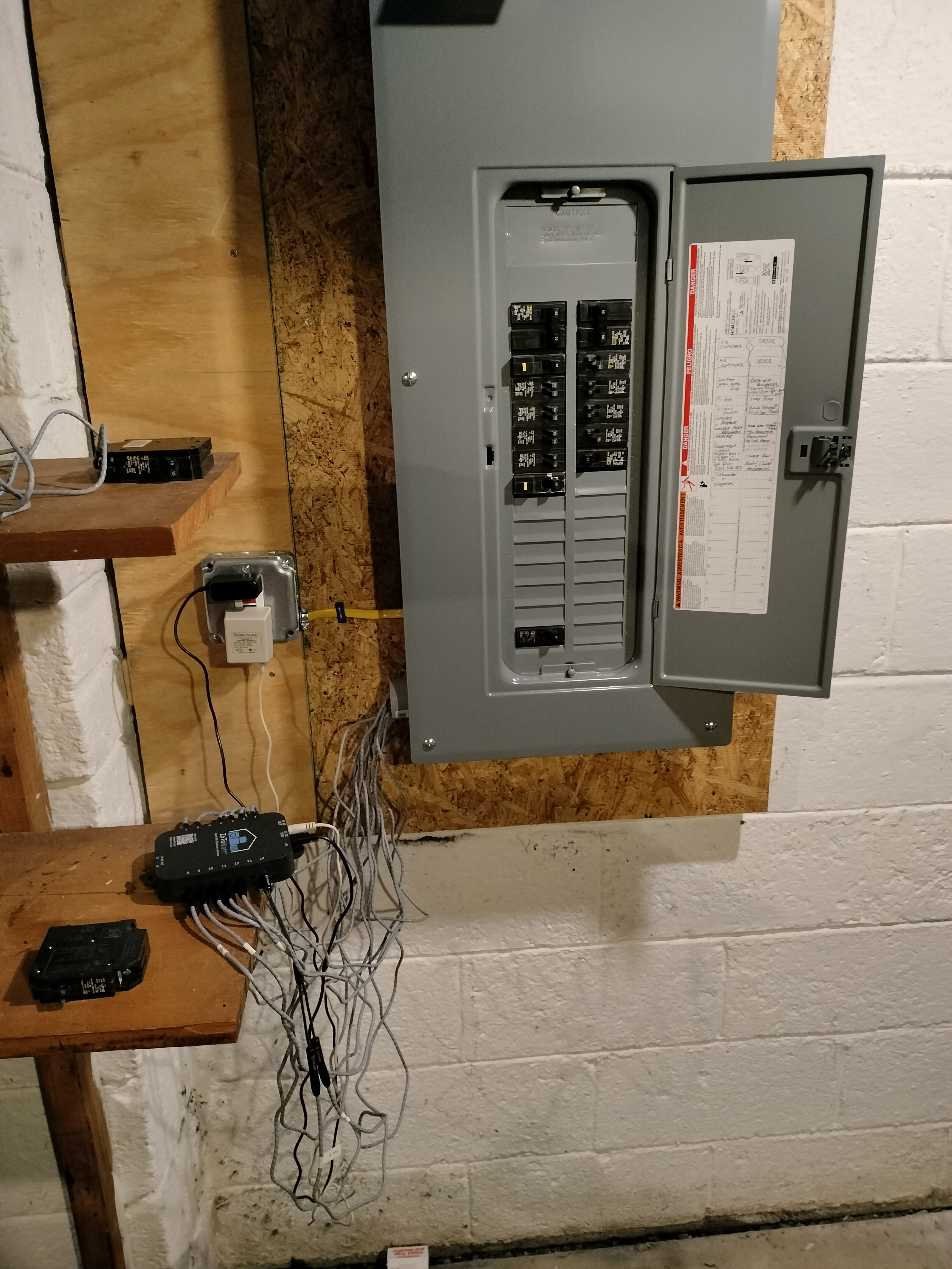
The finished product is bit messy, but A. it's a basement, and B. I can easily run conduit to a box and install everything in there without opening the panel again.