Tuesday, May 23, 2023

Whole home energy monitoring with IoTaWatt

I recently installed an IoTaWatt open source whole home energy monitor, and wanted to summarize my experience and what I learned about the install.

Full disclosure, after I had written this post, but hadn't posted it yet the created of IoTaWatt announced he was stopping production, but continuing to support existing hardware, and working on a new ESP32 based version that he plans to make available as a DIY project.

What is a whole home energy monitor?

A whole home energy monitor is a device that measures all the electrical energy your house uses, both total usage and then usage on individual circuits.  You may have heard of Sense, which is the most well know of these.  Unfortunately, Sense fails my most fundamental rule of smart home tech: it's cloud based.  Which means both that your data will eventually be sold off or leak, and that the device will eventually stop working when the company shuts down the servers.  That's why I insist upon fully local smart home devices.

Why would I want one?

Like most things I do, the answer is data.  Knowing how much energy your house is using can help identify trends and highlight when new devices use a lot of power at idle.  That can help you save money, but realistically you're not going to save enough money to offset the few hundred you spend on the device.  Instead, knowing when circuits are drawing power and how much can help drive automations.

Here are some examples of things I'm detecting or have plans to set up:

  • Know when the hardwired dishwasher is running/done
  • Know when bathroom circuits have a large draw on them (straightener left on)
  • Detect when fridge usage is high for a long time (either door left open, or fridge failing)

There are more examples where I'm instead using a Zigbee smart outlet with energy monitoring to measure just that device (washer, dryer, sump pump).  The IoTaWatt can't replace those smart plugs entirely, as they allow me to measure just one device on a circuit that can have multiple devices on it.  But it is great for measuring the energy usage for either hardwired devices or when you do want an entire circuit at once and can't rely on a smart plug always being used (like the bathrooms example).

A line graph of several circuits being monitored over a day

How does the IoTaWatt work?

All these devices work the same way.  They use Current Transformers (CT) which clip around one of the two wires in a circuit (so either hot or neutral, but not both), and measure the strength of the magnetic field, which increases as the current increases.  There is a base device which you plug in these CTs to, and you tell it what circuit each CT is monitoring and then that reports that usage back to you.

IoTaWatt pros and cons

If you google "best whole home energy monitor" and click on a bunch of lists, you won't even find any the mention IoTaWatt.  I'm sure it comes as no surprise to anyone reading this that I'm using the hipster whole home energy monitor.  I think the main reasons IoTaWatt isn't more popular is that it's more of a DIY solution, as well as the fact that it's a one man operation with 0 SEO or marketing.  That being said, I consider both of those pros.  Here are the pros and cons as I see them, starting with the cons
Cons

  • Less user friendly to set up.
  • Less polished interface.
  • Limited to monitoring 14 circuits, of which 2 are typically your mains, so you really have 12 circuits you can monitor.
  • Must be connected to via WiFi and the antenna is quite weak, will likely require a closer AP/repeater.
  • Not the cheapest option.

Pros

  • Fully local means it will work unless there is a hardware failure.
  • No cloud server to be shut down, and no company to decide they want to start charging a subscription.
  • Made by a guy in New Hampshire, who basically lives on the forums (the fried egg profile) and will provide unlimited, detailed, support.  Often pays for shipping units back to him if he can't figure out what is wrong with it remotely.
  • Very flexible in install and configuration. 

Of the cons, the only big one to me is the 14 (or really 12) circuit limit.  That being said, the bulk of the rest of this post will go into detail on how to mitigate that limit.

Combining circuits

The TL;DR of this is that there are several ways you can combine multiple circuits on one input.  The downside is that you lose the ability to differentiate the circuits you combine, but you often don't really care if you combine them in logical ways.  For example, if you have several bathrooms each with a dedicated circuit, you can combine all of those into one common bathroom input.  You'll lose the ability to know which bathroom the power is being used in, but for most purposes just knowing "all the bathrooms combined are using x watts" is good enough.

How to combine circuits

There are 3 main ways to combine circuits:

  1. Combine them in software
  2. Combine them using a splitter
  3. Put multiple wires in one CT

#1 is the easiest by far, but it doesn't actually save you an input.  You just tell the IoTaWatt to combine inputs 1 and 2 (or whatever).  Not terribly useful, but can be nice to test combining circuits before you try the other two methods out.

#2 is interesting.  It turns out that the CTs just have standard 1/8" stereo headphones plugs on the end of them.  That means you can combine multiple CTs into one input by just using regular, cheap, headphone splitters.  There are a few caveats there, like you need to use identical CTs (size and brand), and each of your CTs need to be sized to handle the combined input of all circuits you are combining.  So, if you are combining two 20 amp circuits, you can't use two 20 amp CTs, you'd have to use two 50 amp CTs since the total power could be 40 amps.  The nice thing about this method is you can combine circuits without opening your service panel again.  You just unplug the CTs from the main IoTaWatt body, plug them both into a splitter, and then plug that splitter into one of the inputs on the IoTaWatt (and tell the software about the new configuration).  You will have to open the service panel to add a new CT if you want to actually use your newly freed up input, but you can combine several and test how they work together over weeks.

#3 has the advantage of being free, but requires the most planning.  You can simply pass multiple wires through the same CT and their current will be summed.  However, they must either be the same phase, or they must be passed through in opposite directions.  Another practical constraint is that the wires need to be physically near each other in the panel.  If you have a panel laid out in an organized way, without much slack, what this means in practice, is that you can only combine circuits in this way if they are on the same side of your panel (left vs right) and the same phase (alternating rows).

This picture from the IoTaWatt docs demonstrates how you can measure two circuits with different phases, by passing one through in the opposite direction.  I don't have slack on any of my circuits to do this kind of thing, but perhaps you do.  Extending circuits inside your panel is a good use for the new Wago inline connectors.

A circuit breaks with 2 wires leaving it looping through a CT in opposite directions

One more note about this picture, is that it's showing a 240V circuit, which uses both phases and so will always have two out of phase circuits that you likely want to combine.  If it is a "pure 240V" circuit then you can just measure one of them and double it in software (which I do for my AC compressor).  However, some 240V circuits also have 120V available, which means there will be one phase with more current than the other, and just doubling will not be accurate, although may be good enough still since the 120V current draw is likely to be quite small.  You can tell if a circuit is pure 240V or 240V plus 120V based on if it has a neutral running to it, or just two hots.  So, 2 wire (plus ground) = pure 240V, but 3 wire (plus ground) = 240V and 120V.

Other thoughts on making 12 inputs work

By combining inputs with either headphone splitters or multiple wires inside one CT you can monitor any number of circuits, at the cost of a loss insight into the individual circuits.  Some other options you have are to combine your two mains, using either of the options just discussed, or to not monitor the mains at all.  There is no reason the IoTaWatt needs to monitor the mains, so if those inputs would be more valuable to you monitoring branch circuits that is an option.  Measuring the mains though allows you to produce an "other" output though.  You can add your two mains together and then subtract each branch circuit input from it.  What is left is all the power your house is using that isn't monitoring by any of your inputs.  That's what I did and my "other" output is quite boring (which is the goal).  I have a roughly constant 14 watt draw on other, and then it spikes when the basement lights go on (which I can monitor being on via a lux meter in the basement).

My install

This is a bit out of order now, but I can't be bothered to copy and paste this section before the previous stuff.

The before state of my service panel

I started with a clean panel which I had rewired when I moved in.  I made a spread sheet of all the breakers, what they had on them, and which physical location and phase they were on, so I could plan which might be combined in one CT.  The IoTaWatt requires two plugs, one for power, and one to use as a reference voltage.  Ideally this is a dedicated circuit so there is less voltage fluctuation as things turn on and off.  I added a dedicated 20 amp outlet right next to my service panel for the IoTaWatt.

I then opened my panel, and began attaching the CTs to the circuits I wanted to measure.  Combining the ones that made sense.  I haven't mentioned this yet, but even for just single wires in a CT the direction of the wire needs to match the phase, or else it will be negative.  Luckily if you mess this up you can just tell the IoTaWatt to flip the value in software.  Still, I put some thought into this at attempted to correctly attach all the CTs in the right orientation from the start. 

Several CTs attached to the hot wires inside my service panel

I knocked out a 1 and 1/4" knockout on the bottom left of the service panel, and put a threaded conduit terminal adapter there to protect the CT wires.  I still don't have the wires in conduit, but when I do that I won't have to open the panel again because I can just unplug the CTs from the IoTaWatt and run them through the conduit and then replug them in.  The important thing is having the terminal piece there.  The 1 and 1/4" conduit is more than enough for the 15 CT wires I have now, 1" may have worked too, but there didn't seem to be much downside to going up to 1 and 1/4" since the knockout I was using went up to that anyway.


My CT wires entering the service panel through a conduit terminal

I should mention that I'm lucky to have a disconnect outside my house by the meter.  When I disconnect that there is no power inside my house, including the service panel.  Normally even with your main break off you still have power where your mains come in.  You can decide if you're comfortable with that, but if not an electrician should be able to install this pretty easily.

My opened service panel with all the CTs added

Another tip, which you can see in the below pic is to label all the CT wires, ideally while you still have the panel opened and as you run each one.  Personally, I just used the notion of which number breaker each was on, using + or , when there were multiple ones.
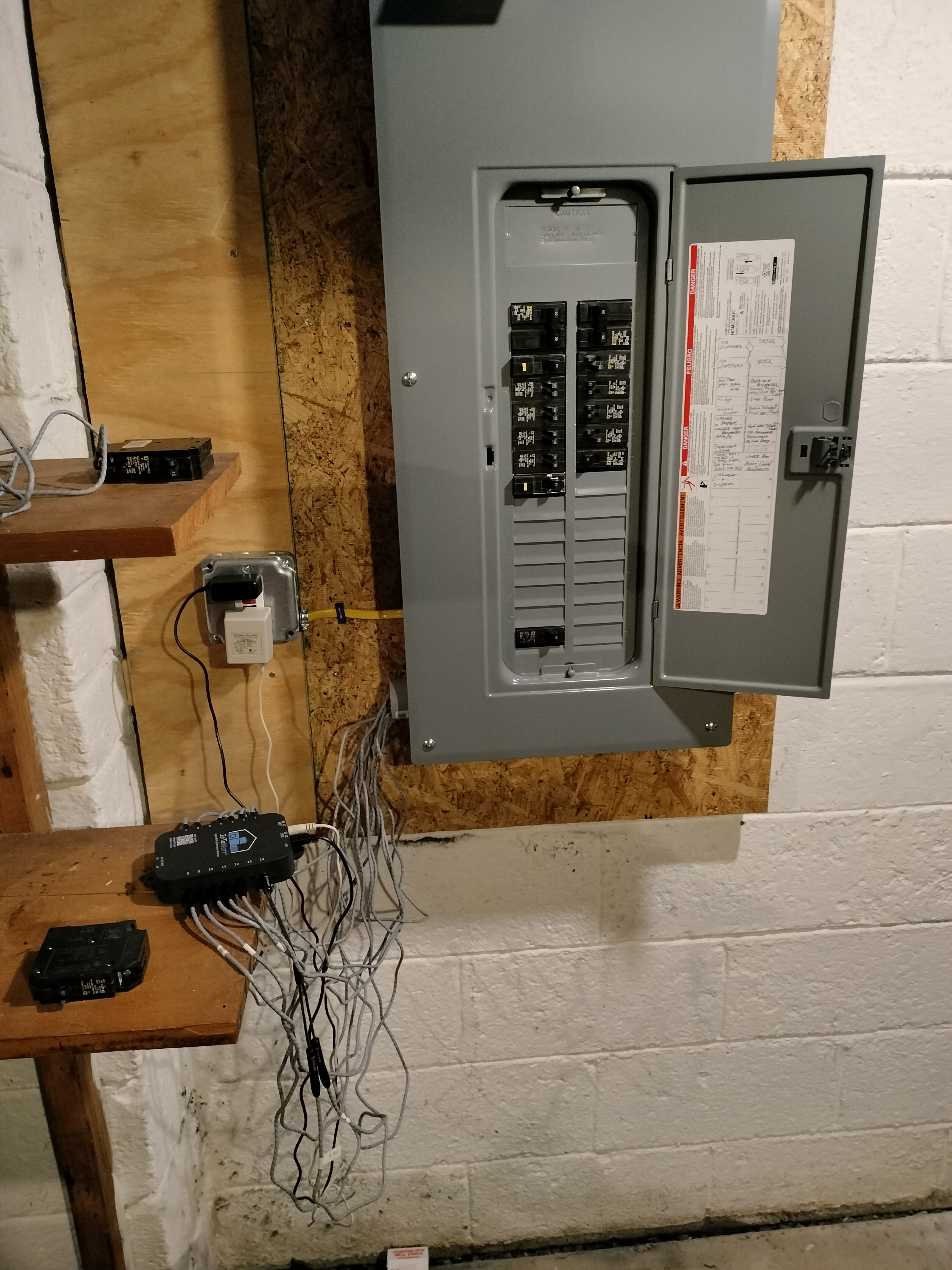
My closed service pane with the IoTaWatt installed


The finished product is bit messy, but A. it's a basement, and B. I can easily run conduit to a box and install everything in there without opening the panel again.

Wednesday, April 12, 2023

Paperclip Game

A browser based text only game where you make as many paperclips as possible.

https://www.decisionproblem.com/paperclips/index2.html

Thursday, March 30, 2023

Turning on my office lights when I plug in my webcam

Another post in my series of "absurdly specific things no other human will ever find useful, but I'm still writing a blog post about".  I have a USB webcam in my home office on my PC which I use for work meetings.  I only plug that webcam in while I'm working, because I don't trust it otherwise.  Also, I have some lights above my desk that I like to turn on during meetings for better lighting.  The switch for those lights is in the corner behind my desk, and annoying to reach.  I installed a smart switch for them so I could turn them on via Home Assistant, but never got around to creating an easier way to turn them on other than the switch, or doing it via the HA UI.  Most mornings I plug in the webcam and then reach awkwardly over my monitors to hit the light switch.

I decided to automate this.  Now while I've recently acquired a glut of motion sensors, I find they have far too many false positives and false negatives to actually drive most automations with.  Instead I figured I could just detect if my webcam was plugged in and if so, send some signal to HA to turn on the light.  My first instinct was a cron job that checked the output of lsusb, which would have worked, but would have been pretty inefficient running every minute, and would have had a lag.  Instead, I began googling how to trigger an action when plugging in a USB device and discovered udev rules.

udev rules

udev rules are a way to trigger commands when various hardware events happen.  They're commonly used for doing certain things when a USB thumb drive is plugged in.  Anyway, I'm going to skip over a lot of saga here, but if you want to read more about udev rules and how to set them up, you can find a lot of info on Google.  Here is one page that describes some of the details a bit.

With that in mind, what I ended up with was a file named /etc/udev/rules.d/80-logitech-webcam-connect.rules with the following contents:
ACTION=="add"    KERNEL=="video0" SUBSYSTEM=="video4linux" SUBSYSTEMS=="usb" ATTRS{idVendor}=="046d", ATTRS{idProduct}=="082c",  RUN+="/home/me/bin/webcam_alert/webcam_alert.sh connect"
ACTION=="remove" KERNEL=="video0" SUBSYSTEM=="video4linux" SUBSYSTEMS=="usb" ATTRS{idVendor}=="046d", ATTRS{idProduct}=="082c",  RUN+="/home/me/bin/webcam_alert/webcam_alert.sh disconnect"


A couple udev protips I figured out.  I know I didn't explain what any of these lines do, but each all caps word (besides RUN) is a filter, which you'll be looking for and then running the command when they all match.   Note the KERNEL=="video0" portion.  The script works without that, but I was getting duplicate executions, which didn't cause any issues but bothered me.

Another thing is that the longest part, by far, of all this was the point where I had all this working, except my shell script was seemingly just silently failing.  It would log to a file fine, but I slowly realized anything that require network access was just timing out.  Turns out this is due to firewall rules that prevent udev rules from connecting to remote machines.  The command sudo systemctl status systemd-udevd.service helped in debugging this, and then the command sudo systemctl edit systemd-udevd.service allowed me to add an exception for the machine that I have running MQTT.

Shell Script

That command will call this shell script.  You can see there is a connect or disconnect argument that is passed to the script.  The script also logs which argument was passed to it, which helps with debugging a lot.  That script is just taking that connect or disconnect argument and turning it into an ON or OFF payload to send to an MQTT sensor in Home Assistant.

MQTT Auto Discovery Sensors

I am a big fan of MQTT auto discovery sensors in Home Assistant.  If you don't know, MQTT is just a protocol for sending messages around your network, which is used heavily by smart home senors, particularly once you get into more DIY stuff.  You set up a "broker" and then devices can publish JSON messages to "topics", which are just file paths.  Then other devices can subscribe to those topics and receive anything published to them.  If you set up MQTT and want to play around with messages or just see what messages are being sent, I recommend MQTT Explorer as a really good GUI tool.

You can get away without any MQTT for a while, but a lot of the more DIY sensors use it, and once you have it set up it unlocks a lot of capabilities.  For example, I'm using it for both ESPHome and Zigbee2MQTT, where I use it to send all data from my zigbee sensors back to HA.  I was hesitant to do that for a while because I assumed it would introduce lag, but I can't detect any delay in something like a door sensor opening and triggering a light to turn on.

Anyway, once you have MQTT set up, you can use a feature of it in Home Assistant called Auto Discovery.  This has to be enabled, but once you do HA will look for topics matching a certain pattern and when it finds them it'll automatically create a new sensor.  Like I said, I'm a big fan of this, and I've made a project that uses it to grab local weather data and send it to Home Assistant.

You can check out the above shell script if you're interesting in making your own custom MQTT auto discovery sensors, it's the simplest I could set it up.  You need to send two different topics, one to configure the sensor and then another for the data.  The script is a bit inefficient in that it sends both the configuration and data every time it runs, but I can live with that considering it only runs a couple times a day.  The weather data project I linked to is a much better done example of MQTT auto discovery sensors.

Home Assistant

At this point it's simple.  The webcam state gets picked up by HA as a binary sensor with an On and Off state.  I just set up an automation to turn on the light via the Lutron integration whenever it transitions from off to on, and vice versa.

For some reason it detects unplugging faster than plugging in, but it's about a second from plugging in to light being on, and just about instant for unplugging.  The timing is a bit of a moot point as it takes a few seconds for Hangouts to detect the camera before I can join a meeting anyway.

Summary

And there you go.  When I plug in my webcam, a custom udev rule triggers, which runs a custom shell script that publishes a MQTT message to a topic which Home Assistant has been configured to automatically detect and treat as a native sensor, and that sensor then triggers an automation which tells the Lutron integration to turn on the lights, simple.  I've been using this for a week now, and it's performed flawlessly, despite the fact that I'm still shocked anytime anything I make works even once.

Tuesday, February 28, 2023

DIY emulation in 2023

Intro

I've been told this is currently the 2020s, and so it's time for my decennial post on how to emulate classic games.  I've been chasing the high of modded original Xboxes running XBMC and a collection of emulators since 2006.  The main selling point of that setup was how slick the interface was.  Just turn it on and do everything with the controller on a UI that was clearly designed for a TV.  The main downside was having a huge Xbox in your living room, and having to use wired controllers.

Last decade's solution was a Raspberry Pi running RetroPie, which worked ok, but the interface was never that great and it struggled with N64.

Separately, the Roku I use to watch Plex, Netflix, and other media is starting to show its age, and I wouldn't mind something more open source.

My plan was to buy a mini PC, put linux on it, maybe some HTPC distro, and use that for both media and emulation.

I'll skip over the saga and say that the media playback didn't work out.  I had assumed there would just be native clients for Netflix and others available, but there isn't.  There are the web versions, and maybe something could be done with launching the web versions seemlessly, but it just didn't feel like it'd ever have the slick UI I wanted.

Incidentally, around this time I got an Nvidia Shield donated to me and discovered SmartTubeNext, which is a Youtube player which skips ads, including portions of the videos about sponsors themselves.  That greatly reduced my desire for media playback on the mini PC.  I've also been very happy with pairing the Shield with an Xbox controller to play game via Steam Link on my Desktop PC.

So what did I end up with?

The focus then was just emulation, from N64 and older.  First, I bought this Mini PC for $200.  Note there are a ton of these around this price point, and they all have similar specs.  I sort of regret buying this one because it has a very loud fan, despite the fact that the listing claimed it was silent when I bought it (and later removed that claim), and because this one doesn't support any sort of Wake On LAN or boot on power restore, so there is no way to for me to turn it on remotely, and I can't leave it on 24/7 because of how absurd the fan is.

I also bought this IR USB dongle for $20.  I intended on setting it all up manually, but ended up just installing the FLIRC program from the repos and liking it a lot.  I set up buttons on my remote to map to Alt+F4 (close program), ESC, and a custom shortcut I set up to show the desktop.  Between those and the obvious stuff like arrow keys and enter, I found it pretty easy to use with a remote.  The only things I have on the desktop are Steam and RetroArch, as well as a few useful tools, including a shortcut to power off.

I was using my Logitech Harmony 300 remote until some of the button finally started to give out.  I replaced that with this remote I got for $40, which I like quite a bit.

I also have this wireless N64 controller that I got for $40, and which you can use with actual N64s or via a USB dongle on a PC.

And I found this amazing archive of every ROM ever on Internet Archive.  I got all the N64 and older ROMs from the systems I wanted, and filtered the sets down to the games I had heard of.

I installed Xubuntu on there, although I'm keeping my eye on KDE's Plasma Bigscreen, which looks very promising for what I want to do, but right now is only available on ARM hardware.

So overall I'm happy with this set up.  I have to get up to turn it on, but after that I can control everything with the remote and controller.  I've been playing a lot of N64 games on it, and they generally work well.  Goldeneye's sound stutters, but I googled what to tweak in the setting to get the best performance out of it, and that was enough to play through the campaign.  Mario 64 I'm about halfway through and it's been flawless.